We explore all kinds of technologies, starting from programming, electronics ending in the photography sector. A bit for everyone.

Wednesday, December 20, 2017

Writing text with the Manim

Hi!

In my previous blog posts, we were setting and running our first example animation with the engine called 'Manim'. The example animation only consisted of drawing a square and transforming it into a circle. This time, I want to try out the so called 'WriteStuff' scene in the example_scenes.py. This scene, for the first time, renders a text with cool vector animation that is unique to 3Blue1Brown.

What's the problem with the 'WriteStuff' scene?
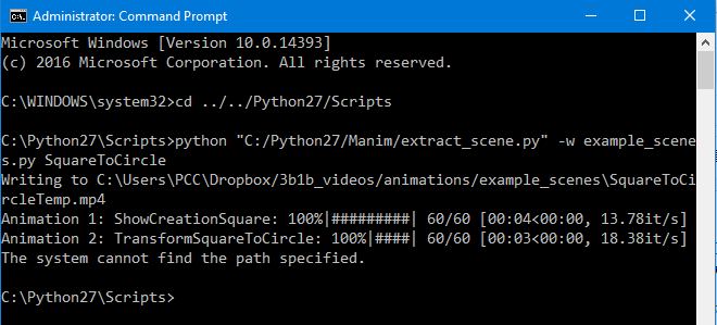
So, if you try running this command:
 python extract_scene.py -p example_scenes.py WriteStuff 
to preview the WriteStuff scene, you would probably see an error that tells you that there is a .svg file missing. This error is caused by the lack of a framework called 'LaTeX' that is used to convert text to .svg files to be able to render the text with all of the cool animations. LaTeX is mentioned as a primary requirement in the readme file on the official GitHub page of the Manim. So, today we are going to install it and test it.

Installing LaTeX

HERE is a link for the setup file, install it just like any other setup. That simple.

Checking if LaTeX works properly

As Anthony Northrup talks about checking if LaTeX and dvisvgm work (it's a LaTeX tool that converts DVI and EPS files to SVG files, hence the name dvi - svg):
Once you've tried to preview/save the WriteStuff scene, you should have a file <NUMBERS>.tex in the /files/Tex directory. If you ran into issues when viewing the scene, try calling the conversion calls (found at the bottom of mobject/tex_mobject.py) manually (but with logging) from the command line. For example:
> cd /files/Tex/
> copy "<NUMBERS>.tex" test.tex
> latex -halt-on-error test.tex
> dvisvgm test.dvi -n -o test.svg
If there aren't any errors at each step, it should convert properly when running via the extract_scenes file, but the dvisvgm might pop an error.

So, what if the dvisvgm pops an error? 

With couple of simple steps you would need to replace the existing dvisvgm tool with the most recent version found HERE (you can also compile from the latest source found here). Choose the correct architecture (32 or 64 bit) and download the .zip archive. There, you will find couple of files including dvisvgm.exe.
Now you will need to use this new version instead of the included version from MiKTeX (or whichever LaTeX installation you are using). To do this, we will need to extract the zip to a folder, then add that folder to the system PATH variable. You can find instructions for doing this here. Once that has been added, you can verify the system is pointing to the updated dvisvgm by opening a new command prompt window (you may have to restart on older machines for the PATH variable to be properly updated) and use the where command:
> where dvisvgm
<THE ABSOLUTE PATH(S) OF dvisvgm IF FOUND>
If the folder you extracted the zip to is at the top, you are ready to test again, otherwise you'll need to fix the PATH.

Now, if you try just the last command, it should work properly converting the dvi to svg.

Try running the preview command again and it would hopefully work:
 python extract_scene.py -p example_scenes.py WriteStuff 


That's it ! You can now render any text you want !
Share:

Monday, December 18, 2017

The Manim -- Follow up

Hi!

This is a follow up blog post for the Manim (the animation engine for explanatory math videos). Today we are going to save the example animation.

So, in the previous blog post, I left you wondering how to save the actual example animation.

After you have done every step carefully and methodically, I assume you can run the command and preview the example animation 'SquareToCircle' in low quality movie format:
 python extract_scene.py -p example_scenes.py SquareToCircle 


Now to actually save it... First, find the 'constants.py' file and in it, change the MOVIE_DIR from
 os.path.join(os.path.expanduser('~'), "Dropbox/3b1b_videos/animations/") 
to 
"<your absolute/fixed output folder path>" 

For example:  "C:/Videos/" 

then try running the command: (Note: that instead of -p we write -w)
 python extract_scene.py -w example_scenes.py SquareToCircle 

You may see an error saying that there is no 'ffmpeg' command. That's because ffmpeg is a framework that needs to be installed and that's fairly easy to do. Just follow the instructions HERE.

After downloading the ffmpeg and adding it to the environmental path variable, you should be good to go. Run the command again and you should see something like this:


Explained by anthonynorthrup314 (Huge shoutout to him for correcting this blog post):

The error you are seeing at the end: The system cannot find the path specified is because it plays a chord when it finishes rendering a scene, you can find this method at the top of the helpers.py file: play_chord(*nums). It tries to call a program play, which isn't installed on Windows. Installing SoX on Linux fixes the problem, but I haven't tried installing it on Windows to actually prove that it will fix the issue. But, in the end, it's nothing to worry about.

Wala!  Now you have created your first movie via The Manim! Congrats!

That's all for today, I'll take a look into the actual code now...
Share:

Animation engine for explanatory math videos -- The Manim

UPDATE: This is an out-dated tutorial, I'm sorry. I'm working on new tutorials...

 
Hi!


I want to make animations for explaining programming concepts and, of course, upload them on my YouTube channel. Watching 3Blue1Brown's YouTube videos, I was wondering how does he make them? If you don't already know, he has a animation engine that he built with python. NOTE: Don't rush it, you are going to have a lot of problems if you do so. Here's the link to his GitHub repository.


one more NOTE: It's going to take you a fair bit of time (couple of hours) setting and learning things up. So, first ask yourself is it worth it! Not saying to discourage, but to warn...

In the process of actually starting it, I downloaded it in my Python27 installation folder (btw, for this to run properly, you need Python 2.7 not the newer 3.6 version). When installing Python, is a VERY good practice (and that's what I did for this tutorial) to add it to the environment path variable (just google - add python to path). When you have downloaded Python27 and the Manim project folder, you can see the required modules for running it in a text file called "requirements.txt". You can see there all of the versions of the modules that are necessary. Here's the catch. You will have a lot of issues with it.

First of foremost, you need to have pip installed, because pip doesn't come with Python27.
The easiest way to install pip (and that's what I did) is to download THIS module in the python folder and run it using the command  python get-pip.py 

Now you have pip installed. The next step is to install every single required module. Here's the catch that I was talking about. In the readme file on the Manim GitHub repository, it's mentioned that you can do this :  pip install -r requirements.txt  but I don't recommend it! Of course first you would need to  cd Scripts  and then using pip, install all requirements manually, by hand and don't forget the version [ EX:  pip install colour==0.1.2  ]. Read them from the text file, one by one and install them. If you have any problems with numpy and scipy, download them individually from HERE as .whl files in the Scripts directory and just run  pip install <the .whl file name>  . This should work without a problem. Of course, keep in mind that you would need to install numpy before scipy.
I would recommend always installing numpy and scipy from the .whl files, because even though I had them both installed, the Manim wouldn't run... As soon as I installed them from the .whl files, everything was working properly.
The last module (aggdraw) is going to require having THIS C++ Compiler Package for Python 2.7 and GitHub installed to be able to clone the repository. I had the GitHub installed on my PC, but if you don't you may try manually downloading and extracting the directory from the link given in the requirements.txt file -- [GitHub link] -- and then manually using pip to installing it. It's a nice thing to have GitHub though, I recommend it every day of the week.

If all of the requirements were installed successfully, you are good to go.

I'll leave you here today...

The next phase is running the Manim from it's project folder
(for me, it's - C:/Python27/Manim - you should be in the folder where you have downloaded Manin)
  python extract_scene.py -p example_scenes.py SquareToCircle  

Thanks for all of the corrections that were suggested by anthonynorthrup314

Next time, will attempt to save the same example animation...
Share:

Friday, September 22, 2017

Arduino: Char Array Problems

While programming an embedded system based on ATmega328p, I have encounter some char array problems in the C programming language.


I had a char array of exactly 8 chars ending with /0:
char a[] = "///////0";
It had trouble reading a[0] many times. For some still unknown reason, when I had:
char a[] = "10000000";
it would corrupt some memory addresses close to the array and it never work as I wanted. The problem is not the '/0' at the end. '/0' it's NOT the null terminator (NUL character in ASCII). The null terminator is '\0'. I tried this with both, the C compiler in the Arduino's native IDE and the C compiler in the Atmel Studio 7 (with the Visual Micro installed) and it was the same exact thing. So, what's wrong? I still don't know, but I'm writing this blog post, because I fixed the problem by adding a random character in the front and in the back that would be never read by any actual code. Just for storing purposes. I can't reveal the whole code, but because of the trouble that I went through I don't recommend using char arrays now at all... :D

The solution code for me was:
char a[] = "/10000000/";

- Mitko
Share:

Tuesday, September 19, 2017

Make a Shutter Release Indicator for any camera!

Following my previous post, I have done and tested a little schematic for a indicator whenever the shutter actuates (whenever the shutter is released). Check the demo video here.

So, we know that the CENTER PIN on the hot-shoe is connected to the GROUND whenever the camera takes a picture (when opening and closing the liveview, that doesn't happen). This automatically triggers the flash. There is a little catch that I explained in the previous blog post.


But this schematic is just good enough for successfully indicating a shutter release. 

As I discussed in the previous blog, the camera keeps the CENTER PIN connected to the GROUND until there is no current flowing to the CENTER PIN i.e. the flash is already triggered. That makes the situation a little bit complicated, so to workaround this issue I have put Q1 transistor to pull the current through the LED to the ground whenever the flash is trigger. That way the LED will flash just for few milliseconds. (I think the schematic is understandable, for any questions, leave them in the comments.)

Some schematic notes:

  • The switch in this virtual schematic acts as the flash triggering IC in the camera. There is no switch in the real world.
  • D1 is the LED which indicates the shutter release. You can put a series resistor for current protection, but because that's just 3V and a small pulse, I had no current limiting resistor.
  • R2 is a current limiting resistor for both, the Q2 and when the shutter is released, the R2 is directly connected to GROUND.
  • R1 is a current limiting resistor too.
That's it! You now have a shutter release indicator that could be used for wireless remote triggering!

Camera used: D5200
Software used to create the schematic diagram: Circuit Wizard

See you next time!
- Mitko
Share:

Sunday, September 17, 2017

How does a DSLR trigger a manual flash unit

If you want to detect a shutter actuation or build a DIY wireless flash trigger, it's not as straightforward as it seems, there is a thing you would need to have in mind.

A week ago, I got my first manual flash (from late 80's). I was worried about putting it on my DSLR, because on few places I read that the so-called "trigger voltages" of some old flashes are 250V which would certainly damage the sensitive electronics in my DSLR. So, I measured the voltage that the flash unit gives between the CENTER PIN and the pin on the side of the hot-shoe mount (GROUND PIN). The voltage was just over 12V, I decided to risk it and put the flash onto the DSLR. And... It worked perfectly fine!

Having a manual flash with just two pins, made me wonder what would it take to trigger the flash with (let's say) Arduino Nano remotely from the camera. From an online schematic, I learned that the flash gets triggered by connecting the CENTER PIN to the GROUND PIN. That easy! It is essentially completing the circuit on one of the transformers side, so the other can light the lamp very brightly. I guessed that there is a transistor in the DSLR that simply connects these pins together.

NOTE: Online I found other schematics which suggest very high voltages through the CENTER PIN, which could be bad for ordinary low voltage low amperage transistors. (That's if you want to put a transistor in between).

Going further, I wanted to learn is this all there is to it (when the camera shutter goes down, the flash is triggered for few milliseconds and than it should go back to normal). But what I discovered is a little bit different...

Here's how I hooked up an LED with a simple 3V battery supply that was acting as a charged flash unit through R1 (47Ohm) directly giving power to the CENTER PIN.


I inserted the modifies hot-shoe on my Nikon D5200 and actuated the shutter once. As predicted the LED turned off, but I guessed just after few milliseconds it will come on again (just like a quick pulse). That never happened. The LED didn't come on until I restarted my power supply. Here's a video of the whole action: https://www.youtube.com/watch?v=Z2YFKX_Ie7E

So what this tells us, is that the camera is pulling through the flash's trigger voltage until the flash is empty (in our case with the battery acting as a flash, until I turn the battery off, the camera is still going to pull the voltage to the ground and not give any to the LED) Then it stops, and of course that flash's going to recharge again. 

If you want to see the LED flash, you would need to use transistors to restart the battery voltage. I don't have currently time for creating a schematic, but it's going to be fairly easy. I just wanted to learn what the camera does and in the future maybe build a DIY wireless flash trigger.

Some other day, I may extend this. It was just a simple learning project for today.
- Mitko
Share:

Tuesday, August 22, 2017

Reverse Engineering a Premiere Pro Plugin

This is a follow-up blog post for the Premiere Pro plugin development.


These days I have been studying the documentation and I have been looking into the example codes. First started looking into the FisheyeUnwrap code and learned a few things about setting up the plugins (Description, Slider Controls, Function Arrangement), but the main code consisted of a complicated mathematics that I'm not interested in. What I was looking for was pixel color manipulation and this FisheyeUnwrap plugin had none to do with it. So, I left it aside.

In this stage, the documentation really helped. I found a table that explains all of the example plugins in the SDK (Page 40 in the Adobe AE SDK). Here, I uncovered that the "Skeleton" plugin in the Templates folder is the best startup plugin for pixel color manipulation.

The next thing I did is copied the Skeleton folder and rename it into my desired plugin name, but that wouldn't change the plugin name. As said in the documentation, you need to replace "Skeleton" to "YourPluginName" and "SKELETON" to "YOUR_PLUGIN_NAME" in every single file in the solution. Don't forget to change the file names too. The best thing to do that is to use either a text editor or the Visual Studio itself. Just go to Edit > Find and Replace > Replace in Files.

The best thing to do now, is try to build it and test the basic in-build functionality of the "Skeleton" plugin in Premiere. The plugin should be called by your plugin name and after the build, the Premiere should recognise it without problems.

The next thing is to finally take a look into the code. The coding style is very annoying for me and one thing that I did on same of the functions is this:


"MySimpleGainFunc16" and "MySimpleGainFunc8" are the main pixel color manipulation functions. In other examples, they are named as "FilterFunc". The 16 and the 8 represent the amount of color information in bits. If you take a look in the Effects folder of the SDK, there is a SDK_Noise plugin. In the SDK_Noise plugin, there are more of these functions - 32bit one, than there is a YUV rendering function and some other non-interesting function (at least, for me)...

I will leave you here, wondering around the functions... Try to find how the inputs affect the color manipulation and try to modify something around. Be careful though... I have still no idea what would happen is there is an error :)

I succeeded in modifying the plugin and got a pretty close result to what I was expecting. It is not difficult at all, just it takes a little bit of time.

Probably I'll do some YouTube series, going through a simple plugin development... Because writing it here, step by step, is pretty exhausting... But still, I'll write here about some the plugins, but more in a short form...

Share:

Sunday, August 20, 2017

Exploring Premiere Pro Plugin Development

Today I decided to check out the Adobe Premiere Pro CC Plugin Development. Here I will just lay out the things that I uncovered during my research and share few tips that you may not have knowed. First of all, every Premiere Pro plugin is programmed in C++ - a language that I'm familiar with. That was nice.

Than I uncovered this SDK (Software Development Kit): https://console.adobe.io/downloads/pr
which I need to look in more deeply.

I put that aside and here's a tip: If you want to learn to program things like plugins that have their own classes and function, the documentation would definitely help you, but you will learn them even faster by looking into examples on GitHub. So that's exactly what I did - I searched on GitHub and here are some nice examples:

https://github.com/apanteleev/FisheyeUnwarp
https://github.com/ThomasSzabo/Minimalistic-Adobe-Premiere-Pro-Panel

Exploring the FisheyeUnwrap, I can see that there is an already .aex file which represents the released and working version of the plugin and there is also just one .cpp file - that I'm pretty sure is the code. Which is awesome! I really like the .README file which apanteleev supplied. It is very nicely and concretely explained.

My concern now is whether or not I can get the SDK to compile my .cpp file and return a .aex file.
What apanteleev mentioned in his .README file is that he used an Adobe After Effects SDK and he provided the link. He said that his plugin should work with either the AE or PP which is kind of weird. I did some further research on this question and It turns out that you can make a CPU Plugin to work with both AE and PP, but if you want to implement a GPU processing, that will just work for the particular product.

I followed the steps that apanteleev wrote:

How to build

  1. Download the After Effects CC SDK for Windows here: http://www.adobe.com/devnet/aftereffects.html
  2. Unpack the SDK into some local folder
  3. Set the AE_PLUGIN_BUILD_DIR environment variable to point to the Adobe plug-ins folder (see above)
  4. Copy the files of this plug-in into Examples\Effect sub-folder of the SDK
  5. Open Win\FisheyeUnwarp.sln solution with Visual Studio 2015 (or downgrade it if necessary)
  6. Build the solution for x64-Release or x64-Debug
  7. Launch After Effects or Premiere Pro. You can launch them from Visual Studio with a debugger attached, for that go to Project properties / Debugging dialog and set Command to the AE / PP executable.

So what I did:
1. Downloaded the SDK
2. Unpacked it in Documents
3. Went to the Environment Variables and set on just like this:

4. Copied his plug-in folder into the Documents/SDK/Examplse/Effects sub-folder
5. Than I opened the Win/FisheyeUnwarp.sln solution with Visual Express 2012 (it should work with other versions too).
6. Now... I went to build the solution and it popped an error:
MSB8020... Ok... I went on stackoverflow and here is a solution that I found: You would need to right-click the project in your solution explorer, go to Properties and change the Platform Toolset to v110. After trying to build the solution again.... An error: MSB4030... Again I went to stackoverflow and here is what I found: Again the same thing - right-click the project in the solution explorer, than go to Properties, than in the Configuration Properties go to Linker, than Debugging and change the Generate Debug Info to true (not Debug).

And.... Success!!! The solution was built without any errors! As I went into the MediaCore folder I saw a .aex file already there. I than started the AE and... whala! There is a plugin now called FisheyeUnwrap! And not just that... The plugin works!

So.. What does this mean? This means that with changing the code in the .cpp file, we CAN create our own plugin for AE and PP! I'm very happy that I managed to build the plugin and that there were no serious errors of sorts. Just to mention that we didn't use the Premiere Pro SDK, but the After Effects CC 2017 SDK. Now the next step is REVERSE ENGINEERING the plugin and learning how the code works and how we can change it to our own needs. But I think for today It's enough, I'll do another follow-up blog post on reverse engineering the plugin. For now, you can follow me on YouTube: Mitko Nikov, Twitter: @mitkonikov. AND AS ALWAYS... EXPLORE DEEPER!


Share:

Contributors

Powered by Blogger.