We explore all kinds of technologies, starting from programming, electronics ending in the photography sector. A bit for everyone.

Thursday, October 22, 2020

Dynamic Programming Explained Simply in 100 Seconds

Dynamic Programming is just a fancy way of saying memoization or caching - remembering stuff to save time later. If you have already computed a function, map the given parameters to the result, and you can use this information later without calculating the whole function again if the parameters are the same.

Those who cannot remember the past are condemned to repeat it. - Dynamic Programming


There are two ways of using dp, one in recursion and the other in iteration


It’s easier to write it in recursion since each time the function gets called you can check whether it’s calculated before.


But often, you will see the iterative approach used because recursion usually takes a lot of stack memory.


For a better understanding of these two approaches, check out the 100 seconds of DP.


Dynamic Programming sounds scary to beginners in competitive programming, but this is the video I wish it existed when I started practising DP. It's a really helpful technique all the time!


Hope you have enjoyed the video!


Share:

Thursday, July 23, 2020

DIY Wireless Follow Focus

Is it possible to build your own homemade, but powerful and feature-packed follow focus? Let's find out!

Youtube video: https://youtu.be/NZtYzvitv3U


The components that I have used include:
  • Nema 17 (but don't use it, I'll explain later!)
  • Driver for the motor
  • two Arduino Nanos
  • two NRF24L01 + PA + LNA
  • Booster if you use 3.3V battery
  • Potentiometer (make sure it's a LINEAR)
  • Plate from SmallRig
  • Rod and Clamp for mounting the motor
  • two generic plastic electronic enclosures

Motor

Regarding the motor, I REALLY don't recommend using the Nema 17 because it's way heavier than it should be. Said that you should look into servo motors from eBay which have their own reduction mechanism. It will allow you to drive heavy lenses but the motor will be way smaller and lighter. If especially you have vintage or Cine lenses, these are designed to be driven easily.

With my setup, I can only use it with the Ronin-M. It does support it but becomes very heavy and hard to use.


Transceiver Module

The other thing you should know is not to use these cheap transmitter/receiver modules, but to invest a dollar or two more into the NRF24L01 + PA + LNA. Even the ordinary NRF24L01 are not good enough for a few meters. Believe me, I have tried them all :/


Potentiometer

Potentiometer choice is also very important. Make sure it's a linear potentiometer between 10K and 100K. I chose a 50K Ohms. You may notice a lot of variation in the voltage that the Arduino will be reading. This is bad. To negate this, you will need capacitors close to the Arduino's powerlines and the Transceiver module. Also, if this doesn't help, you will need to average a couple of readouts from analogue pins over some time. This will certainly help you in the long run.


Don't do it?

In conclusion, If you are looking to beat Tilta or DJI in the weight category, you've already lost. Of course, the money difference is big, but still, if you do this professionally I would recommend going with a factory solution - it will save you from the sweat in the long run. It took me quite a long time to make this. I have posted the code in the Youtube video's description!

If you have any questions regarding my solution, post them below. Make sure you watch the video and hope you have a great day!
Share:

Thursday, March 26, 2020

MemoryRouter and Material UI Navigation

Are you wondering why your MemoryRouter and Navigation from Material UI don't properly work?


Maybe your <BottomNavigation> gets messed up when it's wrapped by a <Link> from react-router-dom?

It took me one day to sort this out. The official documentation of the Bottom Navigation (Action) from MUI is non-existent.

First, you must know that the MemoryRouter is rarely used, because of the server's inability to redirect you to a specific URL. (The URLs are all stored in memory)

However, when you want to use it, here's how to do the Links properly.

return (
    <MemoryRouter>
        <ThemeProvider theme={theme}>
            <Switch>
                <Route exact path="/">
                    <SubjectSelector />
                </Route>
                <Route path="/score">
                    <Scoreboard />
                </Route>
                <Route path="/contribute">
                    <Contribute />
                </Route>
            </Switch>

            <div class="navbar-container">
                <BottomNavigation
                    value={this.state.currentPage}
                    onChange={(event, newValue) => {
                        this.setState({ currentPage: newValue });
                    }}
                    showLabels
                >
                    <BottomNavigationAction
                        component={Link}
                        label="Choose"
                        icon={<SchoolIcon />}
                        to="/"
                    />
                    <BottomNavigationAction
                        component={Link}
                        label="Play"
                        icon={<PlayArrowIcon />}
                        to="/play"
                    />
                    <BottomNavigationAction
                        component={Link}
                        label="Statistics"
                        icon={<BarChartIcon />}
                        to="/score"
                    />
                    <BottomNavigationAction
                        component={Link}
                        label="Contribute"
                        icon={<AddIcon />}
                        to="/contribute"
                    />
                </BottomNavigation>
            </div>
        </ThemeProvider>
    </MemoryRouter>
);

You need to pass the <Link> class as a component prop for the BottomNavigationAction. This way you preserve the integrity of the parent component without disrupting it's CSS classes.
Share:

Saturday, June 30, 2018

Our first open source Premiere Pro CC plugin! - Focus Peaking inside Premiere Pro

Hey!

I'm proud to announce the build and the development of our first open source Premiere Pro CC compatible plugin that mimics the focus peaking function of the Sony mirrorless cameras.

Example

How to use it?

This is the first version of the plugin, so if I add more options, I will have other blogposts explaining them. But for this version, we have several options, the most important one is the Threshold. This option should be always adjusted according to your clip. The higher the threshold, the more sharper details would be 'peaked'. The next option allows you to change the peak color. The last two options are if you want to have only peaks, meaning that everything else is going to be black, or you want to have only peaks, but everything else to be transparent (alpha) - allowing you to add another clip below, or manipulate the quality of the peaks.

Plugin's interface


How to download and install?

If you are here to just download and try the plugin out, here is a FREE DOWNLOAD!
Click on the DOWNLOAD ALL button which would download both of the files in a zip archive. Than, go to Local Disk C > Program Files > Adobe > Common > Plug-ins > 7.0 (or the version you have there) > MediaCore, extract the two files there and you are done! 

Why would I want to use it?

The most obvious reason is to mimic the effect for storytelling purposes, but also, you can use it to check how sharp is your footage and is the focus in the right place.

Open Source?

Yes, it's an open source and here is the link to the GitHub repository!
Share:

Sunday, March 18, 2018

How Nikon battery chargers work?

Hi!

Have you wondered how do Nikon chargers work or, you just want to hack one? This article is all about them.


All this started when I wanted to add 12V support to my Nikon battery charger MH-24 (It charges EN-EL14 model batteries). The reason for adding a 12V support to it is that you can easily charge the batteries in your car. However... And this is big 'however'. Here's why the best thing is to buy an inverter and leave the charger alone.


OPENING THE CHARGER

It's anything but satisfying to open this charger. It has two screws on the back, but it also has couple of grooves that require some brute force to disattach.

Here's the main PCB, the two wires I added afterwards.. 
I'll explain them in a minute.

LET'S ANALYSE IT!

Now's the fun part - analysing the PCB. On the right upper side we have the 220V/110V input going through some noise filters and getting rectified (for the Switch Mode Power Supply ICs). As you can see the PCB is divided into two parts: PRIMARY and SECONDARY. It is essentially a Switch Mode Power Supply (SMPS), but there is a little but important catch! I won't explain in detail how a SMPS works, so if you aren't familiar with it, I recommend reading about it............ Now, you know how a standard SMPS works, but this is a bit different. Knowing that a standard SMPS regulates it's output voltage on the secondary using an optocoupler, we can notice the optocoupler on the rightmost center end of the PCB in the picture above. So, not knowing the following difference in the design, I measured the DC voltage on the secondary coil of the main transformer (it was around 7V) and I build a 12V to 7V regulator using the LM317T.


As you can see on the picture, I attached the regulator after the diode on the secondary coil and turned it on using just 12V input on the regulator. When I tried to test charge the battery, it would charge for couple of seconds and than it would start blinking fast - meaning that something is wrong either with the charger or the battery. So, I wondered why it didn't work...

Here's the catch. There is a no output transistor where the battery is being charged, it's directly connected with the secondary voltage from the power supply. Meaning that the microprocessor regulates the power supply output voltage using the same optocoupler mentioned before to achieve the curve of the battery charge voltage that these lithium batteries want. Meaning, again, that the supply voltage (on the secondary coil) IS NOT CONSTANT, it raises as the battery is being charged.

So, in short, we are screwed. There's no way you can easily add 12V support to this charger (except with an inverter - and that's kind of better because you don't have to add anything to the charger, the inverters are cheap and stable and you could use the inverter not just for charging your batteries, but for anything else.)

That's it folks, I know it's a bummer, but hey, that's a really smart design.
Share:

Wednesday, January 17, 2018

How to: MANY toggle switches on 1 pin of the Arduino


Couple of years ago, I had a project in mind that involved 10 toggle switches that needed to to be connected to the Arduino as the brain of it. So, seeing that I need 10 different pins on the Arduino, I knew that I could devise something up, so that it just uses 1 to 3 pins on the Arduino. My idea is to create an adapter that will convert the toggle switch into a momentary one. And this is exactly what I've created and something even better.


Here's the final waveform that I need to deliver:


Seeing the waveform, you can notice that we need two monostable circuits, one on the rising edge and one on the falling edge to generate two pulses, each when the switch changes position (from OFF to ON or from ON to OFF). So, I constructed this beautiful four transistor schematic that does the exact same thing. Notice that the schematic only consists of transistors, there are no ICs.


NOTICE: This schematic is the correct one, I have removed a resistor from the schematic that I showed on YouTube!

Up there is the toggle switch as an input device and down there is the LED as an indicator. You could directly connect it to a pin on the Arduino. You would need to build a PCB for every switch. Always have in mind the type of the switch (on this schematic, it's the DPST switch, but you could use any other type of toggle switches, as long as you supply opposite potentials on both the bases of the transistors). The length of the pulse is adjusted according the capacitors (on the schematic 47uF). This brings the possibility of connecting as many boards of these as you like in parallel to just one of the pins of the Arduino.

Here's an example waveform with two different toggle switches and how it is possible that the Arduino can detect which one is turned on/off.


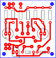
Here's the PCB for it!


Because this is done only using transistors, it's very reliable and fast enough, but it might not be so precise in the timing (It's good enough for the arduino, btw). But if you want to have something that is very precise in the timing, you could use this NE555 Schematic that I devised too.


In most cases you won't need it and it's going to cost you way more.

The PCB that I showed on YouTube is not complete, I needed to put few more pull-down resistors in place, so don't go off and copy it from there. I suggest building your own PCB from this schematic. Maybe sometime in the future I'll update the PCB and upload it here.

I have build both of the schematics on PCBs and they work just fine.
If you have any questions feel free to post them in the comments.
Share:

Monday, January 1, 2018

Color Palette - The Manim

Happy New Year everyone! (if you are reading this in January, at least)

Hi!

As an after-party, writing a bit of code is just enough... :)
Color palettes are very important and essential piece of graphics design. They contribute to the look and feel of the piece. Artists put a lot of effort into creating palettes.
So, I wrote a little script in python that goes through the default color palette and draws the palette on squares, just so we can have a look into the colors whenever we need to pick one.

HERE's a video of that animation.


Taking a look into the script and understanding it will give you a good amount of knowledge that can get you started with coding in the Manim.

This is it for today, I'll see you next time!
Share:

Contributors

Powered by Blogger.