
We explore all kinds of technologies, starting from programming, electronics ending in the photography sector. A bit for everyone.

Saturday, June 30, 2018

Our first open source Premiere Pro CC plugin! - Focus Peaking inside Premiere Pro

Hey!

I'm proud to announce the build and the development of our first open source Premiere Pro CC compatible plugin that mimics the focus peaking function of the Sony mirrorless cameras.

Example

How to use it?

This is the first version of the plugin, so if I add more options, I will have other blogposts explaining them. But for this version, we have several options, the most important one is the Threshold. This option should be always adjusted according to your clip. The higher the threshold, the more sharper details would be 'peaked'. The next option allows you to change the peak color. The last two options are if you want to have only peaks, meaning that everything else is going to be black, or you want to have only peaks, but everything else to be transparent (alpha) - allowing you to add another clip below, or manipulate the quality of the peaks.

Plugin's interface


How to download and install?

If you are here to just download and try the plugin out, here is a FREE DOWNLOAD!
Click on the DOWNLOAD ALL button which would download both of the files in a zip archive. Than, go to Local Disk C > Program Files > Adobe > Common > Plug-ins > 7.0 (or the version you have there) > MediaCore, extract the two files there and you are done! 

Why would I want to use it?

The most obvious reason is to mimic the effect for storytelling purposes, but also, you can use it to check how sharp is your footage and is the focus in the right place.

Open Source?

Yes, it's an open source and here is the link to the GitHub repository!
Share:

Sunday, March 18, 2018

How Nikon battery chargers work?

Hi!

Have you wondered how do Nikon chargers work or, you just want to hack one? This article is all about them.


All this started when I wanted to add 12V support to my Nikon battery charger MH-24 (It charges EN-EL14 model batteries). The reason for adding a 12V support to it is that you can easily charge the batteries in your car. However... And this is big 'however'. Here's why the best thing is to buy an inverter and leave the charger alone.


OPENING THE CHARGER

It's anything but satisfying to open this charger. It has two screws on the back, but it also has couple of grooves that require some brute force to disattach.

Here's the main PCB, the two wires I added afterwards.. 
I'll explain them in a minute.

LET'S ANALYSE IT!

Now's the fun part - analysing the PCB. On the right upper side we have the 220V/110V input going through some noise filters and getting rectified (for the Switch Mode Power Supply ICs). As you can see the PCB is divided into two parts: PRIMARY and SECONDARY. It is essentially a Switch Mode Power Supply (SMPS), but there is a little but important catch! I won't explain in detail how a SMPS works, so if you aren't familiar with it, I recommend reading about it............ Now, you know how a standard SMPS works, but this is a bit different. Knowing that a standard SMPS regulates it's output voltage on the secondary using an optocoupler, we can notice the optocoupler on the rightmost center end of the PCB in the picture above. So, not knowing the following difference in the design, I measured the DC voltage on the secondary coil of the main transformer (it was around 7V) and I build a 12V to 7V regulator using the LM317T.


As you can see on the picture, I attached the regulator after the diode on the secondary coil and turned it on using just 12V input on the regulator. When I tried to test charge the battery, it would charge for couple of seconds and than it would start blinking fast - meaning that something is wrong either with the charger or the battery. So, I wondered why it didn't work...

Here's the catch. There is a no output transistor where the battery is being charged, it's directly connected with the secondary voltage from the power supply. Meaning that the microprocessor regulates the power supply output voltage using the same optocoupler mentioned before to achieve the curve of the battery charge voltage that these lithium batteries want. Meaning, again, that the supply voltage (on the secondary coil) IS NOT CONSTANT, it raises as the battery is being charged.

So, in short, we are screwed. There's no way you can easily add 12V support to this charger (except with an inverter - and that's kind of better because you don't have to add anything to the charger, the inverters are cheap and stable and you could use the inverter not just for charging your batteries, but for anything else.)

That's it folks, I know it's a bummer, but hey, that's a really smart design.
Share:

Wednesday, January 17, 2018

How to: MANY toggle switches on 1 pin of the Arduino


Couple of years ago, I had a project in mind that involved 10 toggle switches that needed to to be connected to the Arduino as the brain of it. So, seeing that I need 10 different pins on the Arduino, I knew that I could devise something up, so that it just uses 1 to 3 pins on the Arduino. My idea is to create an adapter that will convert the toggle switch into a momentary one. And this is exactly what I've created and something even better.


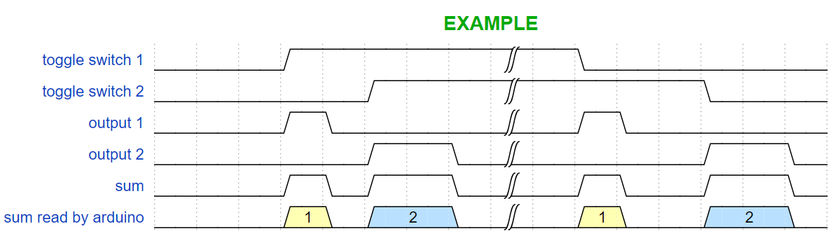
Here's the final waveform that I need to deliver:


Seeing the waveform, you can notice that we need two monostable circuits, one on the rising edge and one on the falling edge to generate two pulses, each when the switch changes position (from OFF to ON or from ON to OFF). So, I constructed this beautiful four transistor schematic that does the exact same thing. Notice that the schematic only consists of transistors, there are no ICs.


NOTICE: This schematic is the correct one, I have removed a resistor from the schematic that I showed on YouTube!

Up there is the toggle switch as an input device and down there is the LED as an indicator. You could directly connect it to a pin on the Arduino. You would need to build a PCB for every switch. Always have in mind the type of the switch (on this schematic, it's the DPST switch, but you could use any other type of toggle switches, as long as you supply opposite potentials on both the bases of the transistors). The length of the pulse is adjusted according the capacitors (on the schematic 47uF). This brings the possibility of connecting as many boards of these as you like in parallel to just one of the pins of the Arduino.

Here's an example waveform with two different toggle switches and how it is possible that the Arduino can detect which one is turned on/off.


Here's the PCB for it!


Because this is done only using transistors, it's very reliable and fast enough, but it might not be so precise in the timing (It's good enough for the arduino, btw). But if you want to have something that is very precise in the timing, you could use this NE555 Schematic that I devised too.


In most cases you won't need it and it's going to cost you way more.

The PCB that I showed on YouTube is not complete, I needed to put few more pull-down resistors in place, so don't go off and copy it from there. I suggest building your own PCB from this schematic. Maybe sometime in the future I'll update the PCB and upload it here.

I have build both of the schematics on PCBs and they work just fine.
If you have any questions feel free to post them in the comments.
Share:

Monday, January 1, 2018

Color Palette - The Manim

Happy New Year everyone! (if you are reading this in January, at least)

Hi!

As an after-party, writing a bit of code is just enough... :)
Color palettes are very important and essential piece of graphics design. They contribute to the look and feel of the piece. Artists put a lot of effort into creating palettes.
So, I wrote a little script in python that goes through the default color palette and draws the palette on squares, just so we can have a look into the colors whenever we need to pick one.

HERE's a video of that animation.


Taking a look into the script and understanding it will give you a good amount of knowledge that can get you started with coding in the Manim.

This is it for today, I'll see you next time!
Share:

Wednesday, December 20, 2017

Writing text with the Manim

Hi!

In my previous blog posts, we were setting and running our first example animation with the engine called 'Manim'. The example animation only consisted of drawing a square and transforming it into a circle. This time, I want to try out the so called 'WriteStuff' scene in the example_scenes.py. This scene, for the first time, renders a text with cool vector animation that is unique to 3Blue1Brown.

What's the problem with the 'WriteStuff' scene?

So, if you try running this command:
 python extract_scene.py -p example_scenes.py WriteStuff 
to preview the WriteStuff scene, you would probably see an error that tells you that there is a .svg file missing. This error is caused by the lack of a framework called 'LaTeX' that is used to convert text to .svg files to be able to render the text with all of the cool animations. LaTeX is mentioned as a primary requirement in the readme file on the official GitHub page of the Manim. So, today we are going to install it and test it.

Installing LaTeX

HERE is a link for the setup file, install it just like any other setup. That simple.

Checking if LaTeX works properly

As Anthony Northrup talks about checking if LaTeX and dvisvgm work (it's a LaTeX tool that converts DVI and EPS files to SVG files, hence the name dvi - svg):
Once you've tried to preview/save the WriteStuff scene, you should have a file <NUMBERS>.tex in the /files/Tex directory. If you ran into issues when viewing the scene, try calling the conversion calls (found at the bottom of mobject/tex_mobject.py) manually (but with logging) from the command line. For example:
> cd /files/Tex/
> copy "<NUMBERS>.tex" test.tex
> latex -halt-on-error test.tex
> dvisvgm test.dvi -n -o test.svg
If there aren't any errors at each step, it should convert properly when running via the extract_scenes file, but the dvisvgm might pop an error.

So, what if the dvisvgm pops an error? 

With couple of simple steps you would need to replace the existing dvisvgm tool with the most recent version found HERE (you can also compile from the latest source found here). Choose the correct architecture (32 or 64 bit) and download the .zip archive. There, you will find couple of files including dvisvgm.exe.
Now you will need to use this new version instead of the included version from MiKTeX (or whichever LaTeX installation you are using). To do this, we will need to extract the zip to a folder, then add that folder to the system PATH variable. You can find instructions for doing this here. Once that has been added, you can verify the system is pointing to the updated dvisvgm by opening a new command prompt window (you may have to restart on older machines for the PATH variable to be properly updated) and use the where command:
> where dvisvgm
<THE ABSOLUTE PATH(S) OF dvisvgm IF FOUND>
If the folder you extracted the zip to is at the top, you are ready to test again, otherwise you'll need to fix the PATH.

Now, if you try just the last command, it should work properly converting the dvi to svg.

Try running the preview command again and it would hopefully work:
 python extract_scene.py -p example_scenes.py WriteStuff 


That's it ! You can now render any text you want !
Share:

Monday, December 18, 2017

The Manim -- Follow up

Hi!

This is a follow up blog post for the Manim (the animation engine for explanatory math videos). Today we are going to save the example animation.

So, in the previous blog post, I left you wondering how to save the actual example animation.

After you have done every step carefully and methodically, I assume you can run the command and preview the example animation 'SquareToCircle' in low quality movie format:
 python extract_scene.py -p example_scenes.py SquareToCircle 


Now to actually save it... First, find the 'constants.py' file and in it, change the MOVIE_DIR from
 os.path.join(os.path.expanduser('~'), "Dropbox/3b1b_videos/animations/") 
to 
"<your absolute/fixed output folder path>" 

For example:  "C:/Videos/" 

then try running the command: (Note: that instead of -p we write -w)
 python extract_scene.py -w example_scenes.py SquareToCircle 

You may see an error saying that there is no 'ffmpeg' command. That's because ffmpeg is a framework that needs to be installed and that's fairly easy to do. Just follow the instructions HERE.

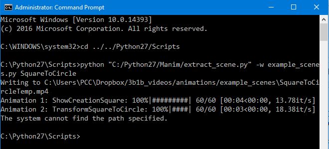
After downloading the ffmpeg and adding it to the environmental path variable, you should be good to go. Run the command again and you should see something like this:


Explained by anthonynorthrup314 (Huge shoutout to him for correcting this blog post):

The error you are seeing at the end: The system cannot find the path specified is because it plays a chord when it finishes rendering a scene, you can find this method at the top of the helpers.py file: play_chord(*nums). It tries to call a program play, which isn't installed on Windows. Installing SoX on Linux fixes the problem, but I haven't tried installing it on Windows to actually prove that it will fix the issue. But, in the end, it's nothing to worry about.

Wala!  Now you have created your first movie via The Manim! Congrats!

That's all for today, I'll take a look into the actual code now...
Share:

Animation engine for explanatory math videos -- The Manim

UPDATE: This is an out-dated tutorial, I'm sorry. I'm working on new tutorials...

 
Hi!


I want to make animations for explaining programming concepts and, of course, upload them on my YouTube channel. Watching 3Blue1Brown's YouTube videos, I was wondering how does he make them? If you don't already know, he has a animation engine that he built with python. NOTE: Don't rush it, you are going to have a lot of problems if you do so. Here's the link to his GitHub repository.


one more NOTE: It's going to take you a fair bit of time (couple of hours) setting and learning things up. So, first ask yourself is it worth it! Not saying to discourage, but to warn...

In the process of actually starting it, I downloaded it in my Python27 installation folder (btw, for this to run properly, you need Python 2.7 not the newer 3.6 version). When installing Python, is a VERY good practice (and that's what I did for this tutorial) to add it to the environment path variable (just google - add python to path). When you have downloaded Python27 and the Manim project folder, you can see the required modules for running it in a text file called "requirements.txt". You can see there all of the versions of the modules that are necessary. Here's the catch. You will have a lot of issues with it.

First of foremost, you need to have pip installed, because pip doesn't come with Python27.
The easiest way to install pip (and that's what I did) is to download THIS module in the python folder and run it using the command  python get-pip.py 

Now you have pip installed. The next step is to install every single required module. Here's the catch that I was talking about. In the readme file on the Manim GitHub repository, it's mentioned that you can do this :  pip install -r requirements.txt  but I don't recommend it! Of course first you would need to  cd Scripts  and then using pip, install all requirements manually, by hand and don't forget the version [ EX:  pip install colour==0.1.2  ]. Read them from the text file, one by one and install them. If you have any problems with numpy and scipy, download them individually from HERE as .whl files in the Scripts directory and just run  pip install <the .whl file name>  . This should work without a problem. Of course, keep in mind that you would need to install numpy before scipy.
I would recommend always installing numpy and scipy from the .whl files, because even though I had them both installed, the Manim wouldn't run... As soon as I installed them from the .whl files, everything was working properly.
The last module (aggdraw) is going to require having THIS C++ Compiler Package for Python 2.7 and GitHub installed to be able to clone the repository. I had the GitHub installed on my PC, but if you don't you may try manually downloading and extracting the directory from the link given in the requirements.txt file -- [GitHub link] -- and then manually using pip to installing it. It's a nice thing to have GitHub though, I recommend it every day of the week.

If all of the requirements were installed successfully, you are good to go.

I'll leave you here today...

The next phase is running the Manim from it's project folder
(for me, it's - C:/Python27/Manim - you should be in the folder where you have downloaded Manin)
  python extract_scene.py -p example_scenes.py SquareToCircle  

Thanks for all of the corrections that were suggested by anthonynorthrup314

Next time, will attempt to save the same example animation...
Share:

Contributors

Powered by Blogger.